One-Finger Cam Lock Tailstock
Cam Lock
Milling Base for Squareness
Set-over
Adjustment Modification
Several designs for cam lock tailstocks have been shared, all of which
appear to work well and greatly enhance the ease and usability of the tailstock,
so we are told. I'd held off making this modification, recently waiting
to see JWE's revisions. I was spurred into action, however, upon
discovering how poorly aligned the
ram of the tailstock was with the lathe centerline. Not just
the adjustable sideways position (set-over), but height and angle (parallelism
with spindle axis). After completing the fix for these problems (another
story, will put a link here later), I tried Bill
Miller's simple yet elegant fix of using a cast off handle from his
toolpost. I made one out of brass
but wasn't satisfied with the outcome.
I was discussing the cam lock feature with a friend, Brett (mill
belt mod guy), who commented it was like a bicycle axle quick release.
BOING! The light went on. No bearings, the cam levers off
of the base only. I tore apart one of my bicycle
quick releases to examine it all closer. So simple its beautiful.
I pondered it a while, pulled out several sizes of drill rod and then started
machining, which is unusual for me because I almost always draw up detailed,
dimensioned drawings before jumping into a major project. On this
one, I didn't even make a sketch.
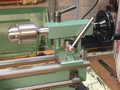
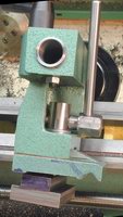
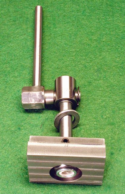
 The completed one-finger cam lock tailstock, in the locked position on
the left and loose on the right. The underside of the lathe ways
are uneven, being thicker at the tailstock end than the headstock end,
which was a problem with the stock tailstock nut/bolt clamp. This
cam lock modification has enough clearance in the loose position that the
bed thickness is no longer an issue.
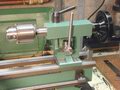
The completed one-finger cam lock tailstock, in the locked position on
the left and loose on the right. The underside of the lathe ways
are uneven, being thicker at the tailstock end than the headstock end,
which was a problem with the stock tailstock nut/bolt clamp. This
cam lock modification has enough clearance in the loose position that the
bed thickness is no longer an issue.
Cam Lock Details
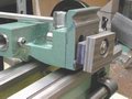
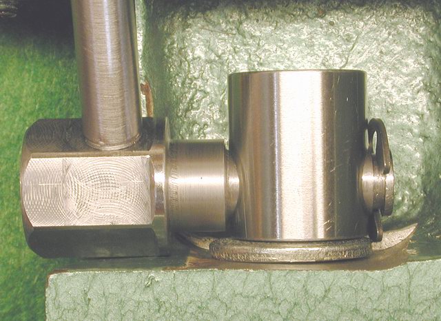
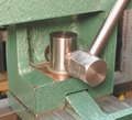 A close-up side view shows it in the mounted position, with the cam, lever,
cam crown and barely visible the retaining ring.
A close-up side view shows it in the mounted position, with the cam, lever,
cam crown and barely visible the retaining ring.
 To access the retaining ring, the cam is rotated to the front, exposing
enough of the ring to pop it on or off, as needed. In use, without
a fix, the cam would be free to flop about. I fixed this by placing
a set screw in the foot plate that holds
the shaft in a fixed orientation. Another way to do this would be
to extend the cam shaft through the back or rear of the tailstock body,
putting the retaining ring where it can be reached a little easier.
The thru hole would not bear any forces other than keeping the lever aligned.
Flash! If a person wanted the handle on the back side of the TS (JWE
style) or under the handle (Corey style), it would be easy to do with this
style, simply by drilling the hole in the TS and making the cam long enough.
This would also put the retaining ring in the front, easy access.
To access the retaining ring, the cam is rotated to the front, exposing
enough of the ring to pop it on or off, as needed. In use, without
a fix, the cam would be free to flop about. I fixed this by placing
a set screw in the foot plate that holds
the shaft in a fixed orientation. Another way to do this would be
to extend the cam shaft through the back or rear of the tailstock body,
putting the retaining ring where it can be reached a little easier.
The thru hole would not bear any forces other than keeping the lever aligned.
Flash! If a person wanted the handle on the back side of the TS (JWE
style) or under the handle (Corey style), it would be easy to do with this
style, simply by drilling the hole in the TS and making the cam long enough.
This would also put the retaining ring in the front, easy access.
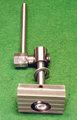
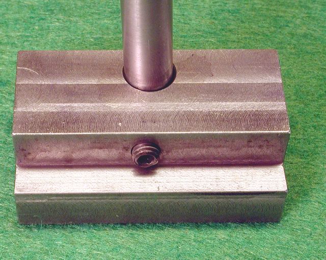
 I had made a new foot plate as part of a different fix. It is made
of cast iron and fills the available space under the ways, leaving only
enough clearance as necessary for free sliding. I was trying to increase
the weight of the base to counterbalance the upper tailstock.. The
stock tailstock always tipped over frontwards, particularly with a drill
chuck mounted.
I had made a new foot plate as part of a different fix. It is made
of cast iron and fills the available space under the ways, leaving only
enough clearance as necessary for free sliding. I was trying to increase
the weight of the base to counterbalance the upper tailstock.. The
stock tailstock always tipped over frontwards, particularly with a drill
chuck mounted.
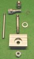
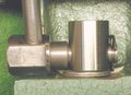
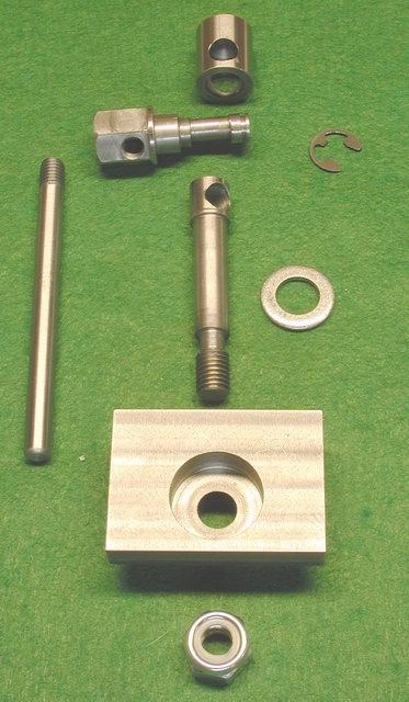
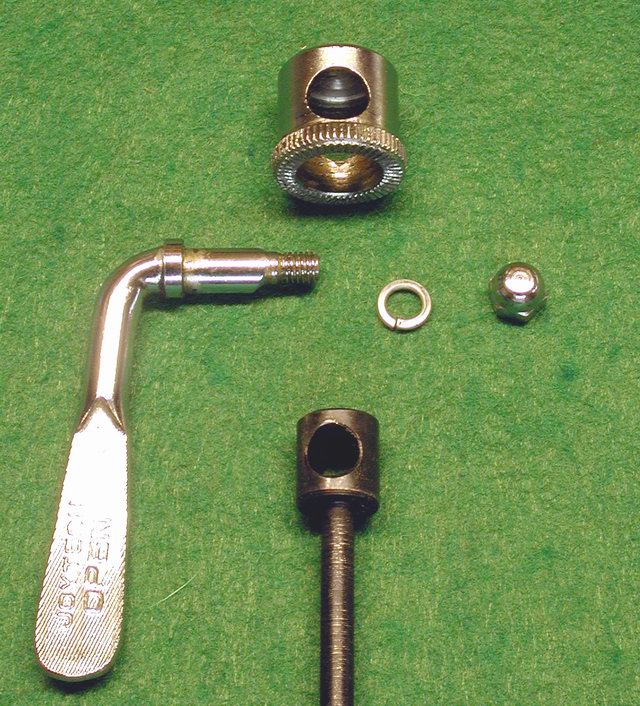
 The parts are fairly simple to make, the cam being the most difficult.
Adjustability of the position of the lever when the cam is locked is afforded
by the nylon stop nut on the under side of the foot plate. This is
an extension of Bill Miller's brilliance of cutting down the stock foot
plate to a smaller square and recessing the new foot plate so the bolt
could be rotated in 90 degree increments. With the stop nut there
is unlimited adjustability.
The parts are fairly simple to make, the cam being the most difficult.
Adjustability of the position of the lever when the cam is locked is afforded
by the nylon stop nut on the under side of the foot plate. This is
an extension of Bill Miller's brilliance of cutting down the stock foot
plate to a smaller square and recessing the new foot plate so the bolt
could be rotated in 90 degree increments. With the stop nut there
is unlimited adjustability.
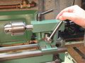

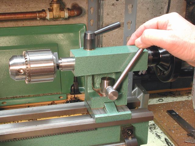
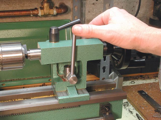
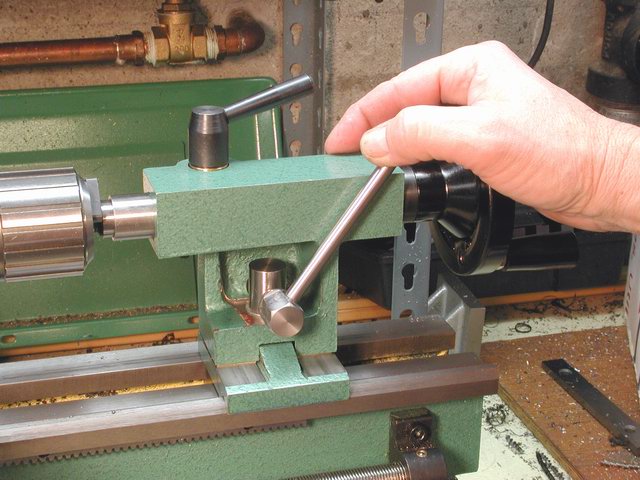
 An unexpected delightful feature with this type of cam lock is that it
can be operated with one finger only while resting your hand on the tailstock
crank, moved and relocked, again with one hand/one finger. Here,
the starting position the cam is locked. Second photo shows the cam
released with the thumb and the tail moved forward, followed by locking
the cam again using only the thumb. I did not design or intend for
it to be this way, it is just a serendipitous but very useful feature.
An unexpected delightful feature with this type of cam lock is that it
can be operated with one finger only while resting your hand on the tailstock
crank, moved and relocked, again with one hand/one finger. Here,
the starting position the cam is locked. Second photo shows the cam
released with the thumb and the tail moved forward, followed by locking
the cam again using only the thumb. I did not design or intend for
it to be this way, it is just a serendipitous but very useful feature.
The cam lock has proved to effectively hold the tailstock in place.
Only once since making this modification has the cam failed to hold while
drilling and that was a 1/2" hole. Simply snugging up on the locking
lever was enough to secure it. Part of this modification included
squaring
up the tailstock base castings so the tailstock ram was properly aligned
with the spindle axis. After completing the base squaring fix and
cam lock, I modified the set-over
adjustment which turned out great and completed my modifications of
the tailstock for now.
Post comments on the group or email directly to me, krugerr@easystreet.com
Rick Kruger
Portland, OR
revised April 1, 2002

 The completed one-finger cam lock tailstock, in the locked position on
the left and loose on the right. The underside of the lathe ways
are uneven, being thicker at the tailstock end than the headstock end,
which was a problem with the stock tailstock nut/bolt clamp. This
cam lock modification has enough clearance in the loose position that the
bed thickness is no longer an issue.
The completed one-finger cam lock tailstock, in the locked position on
the left and loose on the right. The underside of the lathe ways
are uneven, being thicker at the tailstock end than the headstock end,
which was a problem with the stock tailstock nut/bolt clamp. This
cam lock modification has enough clearance in the loose position that the
bed thickness is no longer an issue.


