MiniMill Belt Drive Modification
MiniMill Belt Drive Modification
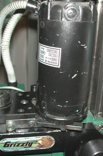
The stock Grizzly MiniMill
is geared between the motor and spindle head gear train, providing a direct
drive rather than belt drive like many larger mills.. Crashing or
stalling the MiniMill can have disasterous consequences, as several have
discovered, breaking those gears, which would likely not occur if it were
belt driven.
Gear Drive
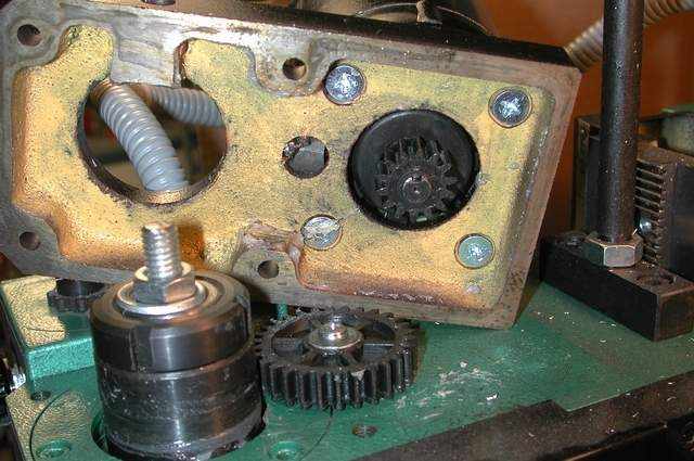
When the mill crashes or stalls, gear damage can occur, in the form
of stripped, broken or cracked gears. Aside from my day job as Service
Manager for a major metropoitan bicycle chain, at home I make specialty
bicycle tools. In doing this, I take aggressive cuts, flycut and
tap on the minimill, so when this happened to my mill, I decided to fix
it by converting it to a belt drive. The whole thing took about two
hours. Since making this modification, I have not lost any time machining
due to gear problems.
Belt Drive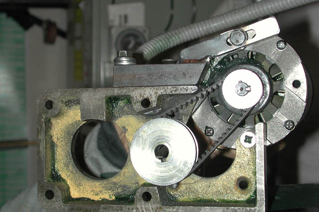
Making this modification involved these major steps:
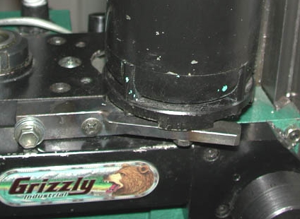
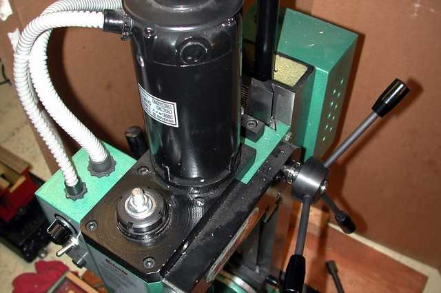
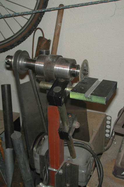
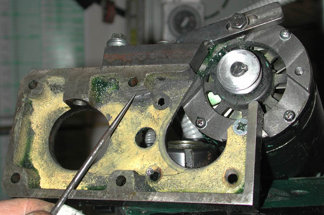
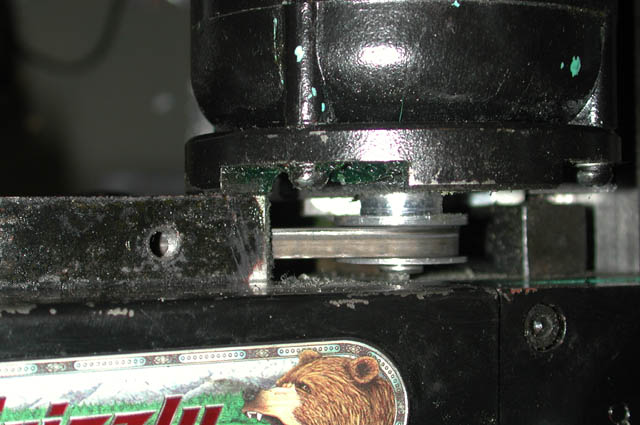
Due to the size of the toothed belt, it was necessary to offset the new motor postion, to the rear and right (or left, your choice), outside the dimensions of the stock motor mount. This meant cutting out a corner of the stock motor mount. The belt drive picture immediately above shows the right rear corner of the stock motor mount removed, about where the smaller pulley is located. I did this using a home-built grinder/cuttoff wheel/polishing arbor, based on an R8 Collet spindle with interchangeable arbor/wheels and a 3/4" arbor diameter.
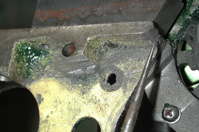
Portions of the motor mount housing (A and B) needed to be relieved of some metal for belt clearance.
Making The Pulleys
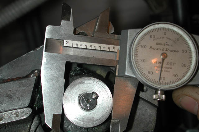
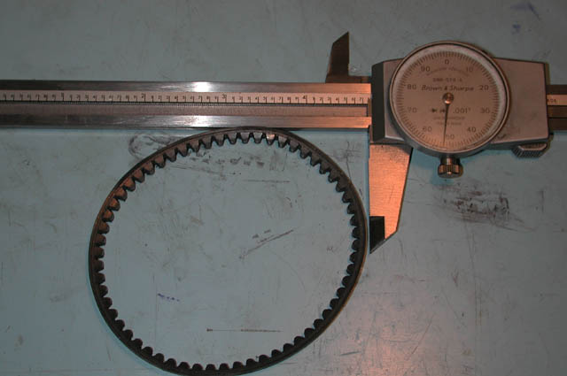
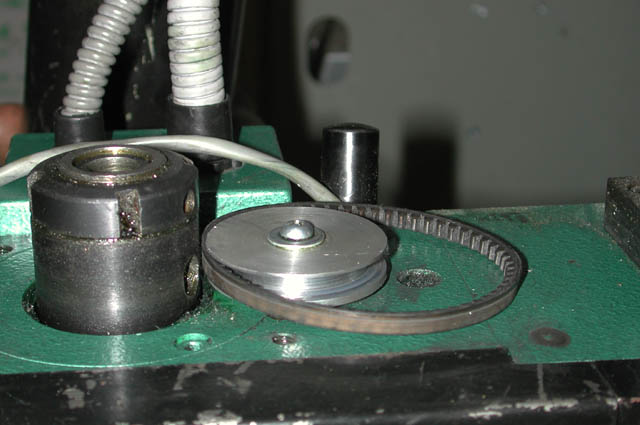
Because I was in a hurry, I machined both of the pulleys out of some scrap aluminum on hand. I found the thinnest sewing machine drive belt I could, as the space under the motor mount plate is limited. Total length of the belt is about 10", measured by squeezing the belt together into a straight, flat pair and measuring the lenght, which is about 1/2 the total circumference. The measurement (0.485") and belt are show after releasing the squeeze on the belt.
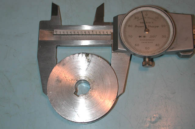
Dimensions of the two pulleys were very close to the gears they replaced.
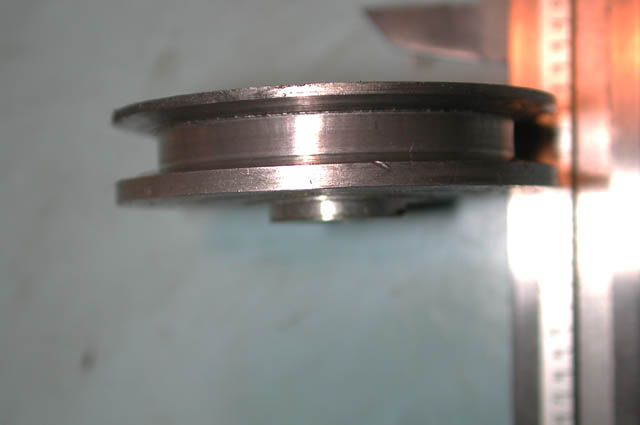
Large Pulley
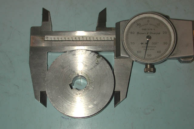 OD
is about 1.850" and the groove
diameter is about 1.500". For the belt
groove, I ground the form tool, comparing the angles to the belt as
I went.
OD
is about 1.850" and the groove
diameter is about 1.500". For the belt
groove, I ground the form tool, comparing the angles to the belt as
I went.
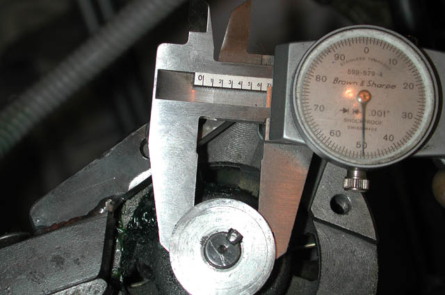
Little Pulley
 OD
is about 1.050" and the groove
diameter is about 0.650". Both pulleys can probably be purchased
from major suppliers like W.M.Berg (www.wmberg.com) and Stock Drive Products
(www.sdp-si.com), but I wanted my machine back in operation and didn't
want to wait for deliveries.
OD
is about 1.050" and the groove
diameter is about 0.650". Both pulleys can probably be purchased
from major suppliers like W.M.Berg (www.wmberg.com) and Stock Drive Products
(www.sdp-si.com), but I wanted my machine back in operation and didn't
want to wait for deliveries.
Remounting the Motor
Motor Bracket
 Installing
the belt drive meant relocating the motor mount back
and to the side in order to achieve belt tension. This also meant
cutting out a corner of the
mounting plate and necessitated fabrication of a new mounting
bracket.
Installing
the belt drive meant relocating the motor mount back
and to the side in order to achieve belt tension. This also meant
cutting out a corner of the
mounting plate and necessitated fabrication of a new mounting
bracket. 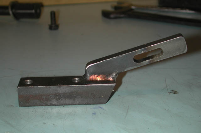
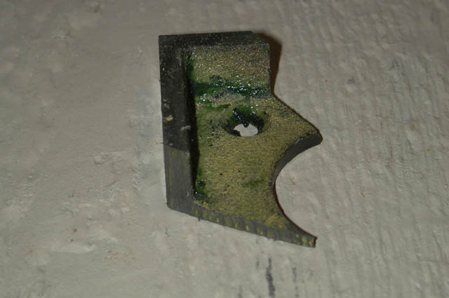
The slot in the bracket allows for adjusting tension on the belt.
I didn't have a rotary table or other means to mill a curved slot, so the
slot in this bracket is slightly oversized to allow for sidways movement
during belt adjustment.
Reversing Switch
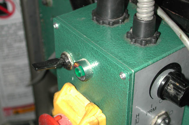
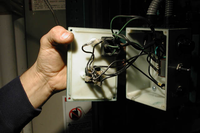 Replacing
the geared drive with the pulley/belt drive caused the spindle rotation
to be reversed. So, I had to rewire the control electronics to reverse
the motor rotation in order to have the spindle turning in a clockwise
direction so mill cutters would work. I also wanted the mill to be
reversible, so that I could do tapping. To accomplish this, I installed
a double throw, 4-pole switch
that
permits reversing the mill just like the minilathe.
Replacing
the geared drive with the pulley/belt drive caused the spindle rotation
to be reversed. So, I had to rewire the control electronics to reverse
the motor rotation in order to have the spindle turning in a clockwise
direction so mill cutters would work. I also wanted the mill to be
reversible, so that I could do tapping. To accomplish this, I installed
a double throw, 4-pole switch
that
permits reversing the mill just like the minilathe.