Milling the Tailstock Base to Square it Up
A question
was asked recently on the Minilathe grouprecently about how to mill the
tailstock base so the ram stays parallel to the lathe bed, saying there
was a URL posted about doing it but didn't provide details enough for a
newbie to figure it out. Just what URL was being reference is unclear
as the URL was not included. I milled my tailstock base during the
process of making a cam-lock
and making a button-type
set-over adjustment and posted a couple pages about it, so if the comments
were about lack of information on my pages, here is a supplement on milling
the base to square it up with the lathe bed.
There were two primary difficulties to holding, measuring and milling
the upper and lower tailstock castings, how to hold them in the mill to
ensure proper alignment of the surfaces to be milled. I had previously
posted a page showing how I indicated
the tailstock castings to determine how badly they were out of square
with the late bed, being a surrogate with the lathe spindle axis, which
is what it really needs to be aligned with. Indicating of the base
was done on the lathe bed, which kept the base aligned by the Vee way and
flat way. This wasn't available when holding the base in the
mill vise.
Milling the Tailstock Base
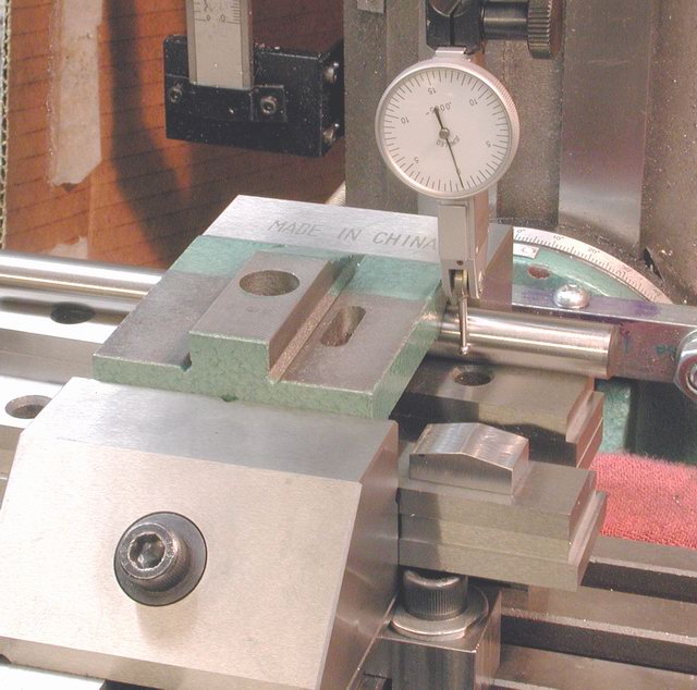
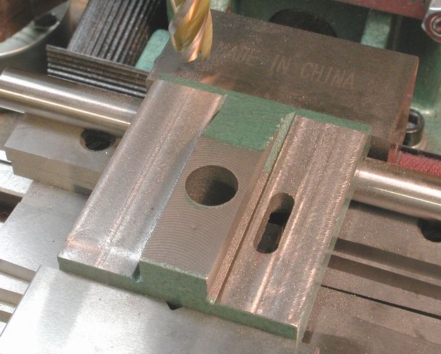
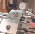 I used what I think of as a three point locating method, using a 1/2" reamer
blank in the inverted Vee and a pointed block of steel under the middle
of the flat way. The indicator was set up on the side of the reamber
blank and the mill vise adjusted until the reading on both sides of the
base were equal. To switch sides the spindle was raised, table moved,
spindle lowered until the highest reading on the opposite side was obtained.
The small house shaped block of steel resting on the front parallel in
the photo was the single resting point for the flat way. Determining
the height of this house shaped block was a tedious process, that I don't
recall clearly, perhaps because it was so tedious. I don't have any
photos, but what I recall is that I indicated the front and rear top sides
of the base while on the lathe bed and noted the readings. Then,
on a surface plate, with the base resting on the reamer blank, I used a
small adjustable parallel under the flat way to raise and lower the rear
of the base until I could duplicate the relative indicator readings on
the front and rear. I measured the thickness of the adjustable parallel
and milled the peak of the block to that measurement. I used a pointed
block the alignement of the base would be wholly determined by the reamer
blank/Vee way and not the flat way.
I used what I think of as a three point locating method, using a 1/2" reamer
blank in the inverted Vee and a pointed block of steel under the middle
of the flat way. The indicator was set up on the side of the reamber
blank and the mill vise adjusted until the reading on both sides of the
base were equal. To switch sides the spindle was raised, table moved,
spindle lowered until the highest reading on the opposite side was obtained.
The small house shaped block of steel resting on the front parallel in
the photo was the single resting point for the flat way. Determining
the height of this house shaped block was a tedious process, that I don't
recall clearly, perhaps because it was so tedious. I don't have any
photos, but what I recall is that I indicated the front and rear top sides
of the base while on the lathe bed and noted the readings. Then,
on a surface plate, with the base resting on the reamer blank, I used a
small adjustable parallel under the flat way to raise and lower the rear
of the base until I could duplicate the relative indicator readings on
the front and rear. I measured the thickness of the adjustable parallel
and milled the peak of the block to that measurement. I used a pointed
block the alignement of the base would be wholly determined by the reamer
blank/Vee way and not the flat way.
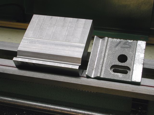
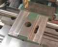 Milling the base top and boss was a trivial task once the base was aligned.
I believe this aligned the base in three planes, X, Y and Z. The
boss was milled on the front and rear sides. Althought the underside
of the base was very crudely machined, I did not attempt to make any
improvements. The larger block next to the stock base is an alternate
base I had started, intending to replace the stock base, but ultimately
stayed with the stock base.
Milling the base top and boss was a trivial task once the base was aligned.
I believe this aligned the base in three planes, X, Y and Z. The
boss was milled on the front and rear sides. Althought the underside
of the base was very crudely machined, I did not attempt to make any
improvements. The larger block next to the stock base is an alternate
base I had started, intending to replace the stock base, but ultimately
stayed with the stock base.
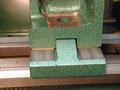
Milling the Tailstock Ram Casting
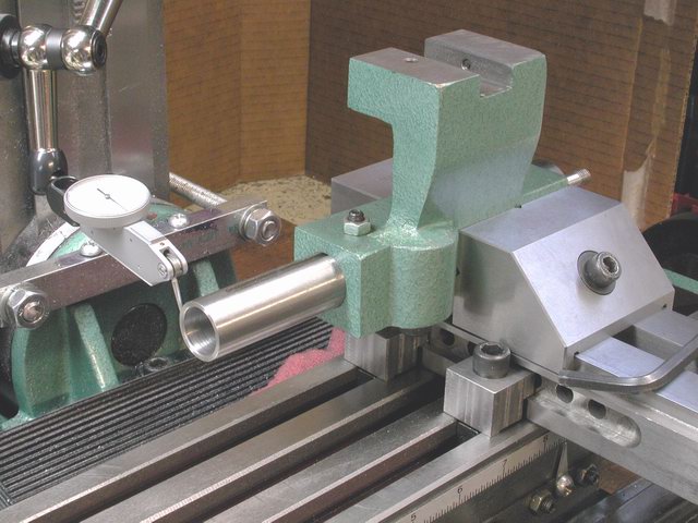
 Clamping and indicating the ram slide was challenge as well. In my
initial holding and indicating, I'd held the tailstock by the ram
in Vee blocks, which clearly would not work for milling. Instead,
I held the upper tailstock upside down, by the sqaure sides of the ram
housing and indicated on the extended ram. I'd locked the ram clamp
with a SHCS prior to clamping it in the vise. The indicator was brought
up against the ram and the spindle raised/lowered to get the maximum reading,
which located the center of the ram. Then the table was moved to
the other end of the ram, the raising and lowering repeated and the maximum
reading noted. By indicating both the side of the ram and the top
of the ram, the casting was adjusted in the vise and the position of
the vise adjusted until the ram was aligned vertically and laterally.
Clamping and indicating the ram slide was challenge as well. In my
initial holding and indicating, I'd held the tailstock by the ram
in Vee blocks, which clearly would not work for milling. Instead,
I held the upper tailstock upside down, by the sqaure sides of the ram
housing and indicated on the extended ram. I'd locked the ram clamp
with a SHCS prior to clamping it in the vise. The indicator was brought
up against the ram and the spindle raised/lowered to get the maximum reading,
which located the center of the ram. Then the table was moved to
the other end of the ram, the raising and lowering repeated and the maximum
reading noted. By indicating both the side of the ram and the top
of the ram, the casting was adjusted in the vise and the position of
the vise adjusted until the ram was aligned vertically and laterally.
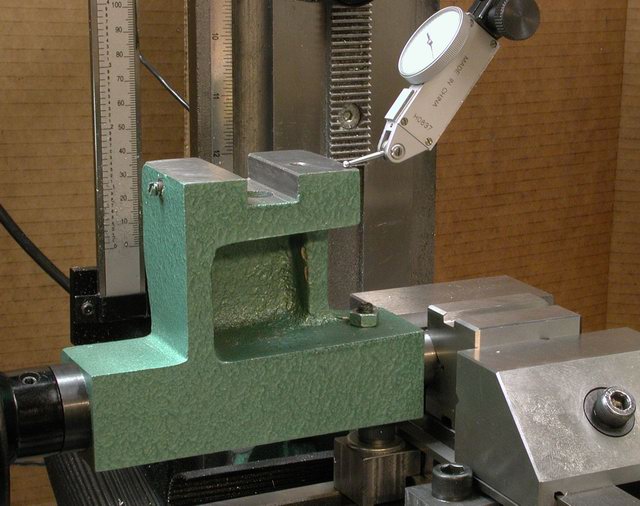
Shimming for Final Alignment
 Milling the under side of the tailstock casting and the recess for the
boss was a simple finishing task. Brass shims were placed between
the castings to aligne the ram with the lathe spindle. Brass shims
were also placed behind thre rear boss, but that was more to protect the
boss from the set-over setscrews than alignment.
Milling the under side of the tailstock casting and the recess for the
boss was a simple finishing task. Brass shims were placed between
the castings to aligne the ram with the lathe spindle. Brass shims
were also placed behind thre rear boss, but that was more to protect the
boss from the set-over setscrews than alignment.
Hopefully, this provides enough information on the "how to". Your
questions and comments are welcomed.
Rick Kruger
krugerr@easystreet.com
BACK to Cam Lock Page
Tailstock Set-Over Page
Indicating Base
Page
 I used what I think of as a three point locating method, using a 1/2" reamer
blank in the inverted Vee and a pointed block of steel under the middle
of the flat way. The indicator was set up on the side of the reamber
blank and the mill vise adjusted until the reading on both sides of the
base were equal. To switch sides the spindle was raised, table moved,
spindle lowered until the highest reading on the opposite side was obtained.
The small house shaped block of steel resting on the front parallel in
the photo was the single resting point for the flat way. Determining
the height of this house shaped block was a tedious process, that I don't
recall clearly, perhaps because it was so tedious. I don't have any
photos, but what I recall is that I indicated the front and rear top sides
of the base while on the lathe bed and noted the readings. Then,
on a surface plate, with the base resting on the reamer blank, I used a
small adjustable parallel under the flat way to raise and lower the rear
of the base until I could duplicate the relative indicator readings on
the front and rear. I measured the thickness of the adjustable parallel
and milled the peak of the block to that measurement. I used a pointed
block the alignement of the base would be wholly determined by the reamer
blank/Vee way and not the flat way.
I used what I think of as a three point locating method, using a 1/2" reamer
blank in the inverted Vee and a pointed block of steel under the middle
of the flat way. The indicator was set up on the side of the reamber
blank and the mill vise adjusted until the reading on both sides of the
base were equal. To switch sides the spindle was raised, table moved,
spindle lowered until the highest reading on the opposite side was obtained.
The small house shaped block of steel resting on the front parallel in
the photo was the single resting point for the flat way. Determining
the height of this house shaped block was a tedious process, that I don't
recall clearly, perhaps because it was so tedious. I don't have any
photos, but what I recall is that I indicated the front and rear top sides
of the base while on the lathe bed and noted the readings. Then,
on a surface plate, with the base resting on the reamer blank, I used a
small adjustable parallel under the flat way to raise and lower the rear
of the base until I could duplicate the relative indicator readings on
the front and rear. I measured the thickness of the adjustable parallel
and milled the peak of the block to that measurement. I used a pointed
block the alignement of the base would be wholly determined by the reamer
blank/Vee way and not the flat way.