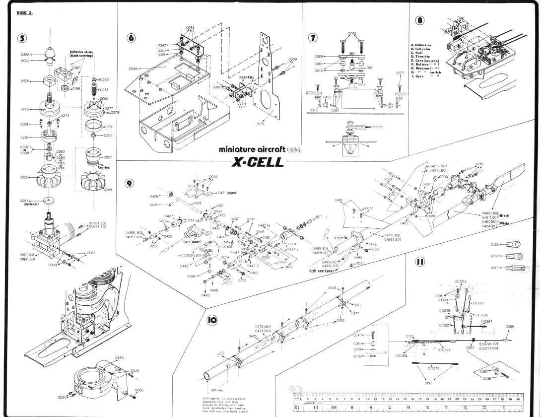
XCell 60 Assembly & Maintenance Page
Assembly Manual ( Flip Through )
or Individual IMAGES ONLY
Rotor Head Hub - 1
Rotor Head - 2
Upper Frame & Collective - 3
Frame Tail Drive - 4
SeeSaw, Swash & Drive Gear - 5
Main Frames - 6
Engine Fan & Clutch - 7
Cooling Shroud - 8
Landing Gear - 9
Collective Servo - 10
Servo Placement - 11
Servo Tray Assy - 12
Lower Tray Assy - 13
Fuel Tank Assy - 14
Tail Rotor Assy - 15
Tail Boom & Drive - 16
Tail Rotor & Boom - 17
Boom Support Assy - 18
Push Rod Location - 19
Push Rod Lengths - 20
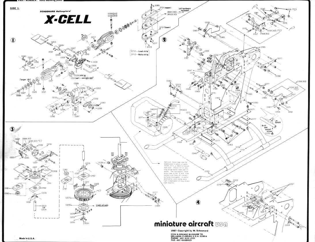
Full Plan Page 1
Full Plan Page 2
You are Visitor number
since 11/18/1998
For more information email me at:
pth3k@virginia.edu